General Planar Motion

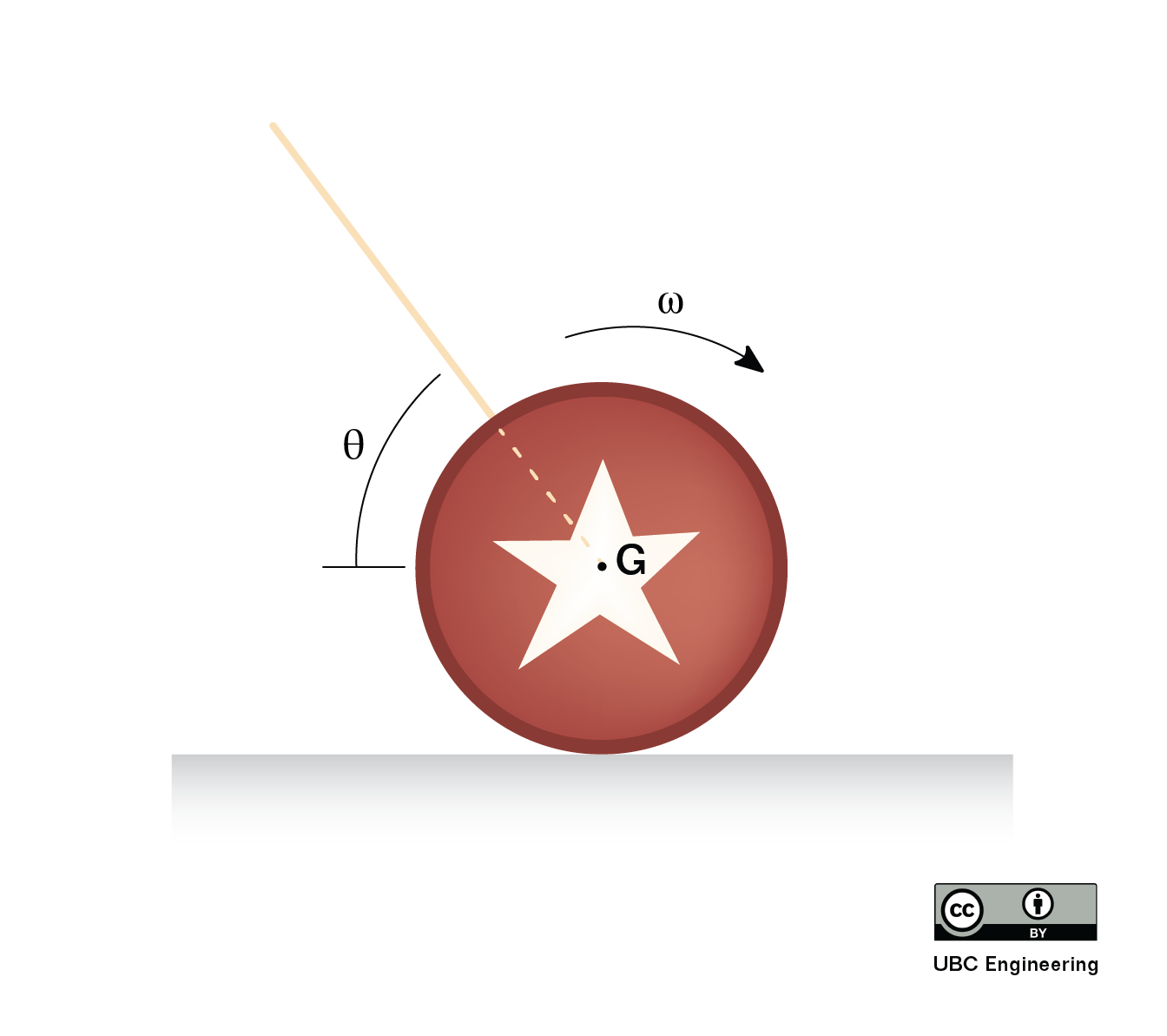
In general planar motion, bodies are both rotating and translating at the same time. As a result we will need to relate the forces to the acceleration of the center of mass of the body as well as relating the moments to the angular accelerations.

A child rolling a tire along a beach
This tire being rolled along the ground is an example of general planar motion. The tire is both translating and rotating as it is pushed along. Image by Joy Agyepong CC-BY-SA 4.0.

To analyze a body undergoing general planar motion, we will start by drawing a free body diagram of the body in motion. Be sure to identify the center of mass, as well as identifying all known and unknown forces, and known and unknown moments acting on the body. It is also sometimes helpful to label any key dimensions as well as using dashed lines to identify any known accelerations or angular accelerations.

Next we move onto identify the equations of motion. At the core of this, we will go back to Newton's Second Law. Since this is a rigid body system, we include both the translational and rotational versions.

\[\sum \vec{F}=m*\vec{a_G}\]
\[\sum \vec{M_G}=I_G*\vec{\alpha}\]

As we did with the previous translational systems, we will break the force equation into components, turning the one vector equation into two scalar equations. Additionally, it's important to always use the center of mass (G) for the accelerations in our force equations and take the moments and moment of inertia about the center of mass for our moment equation.

\[\sum F_{x}=m*a_{Gx}\]
\[\sum F_{y}=m*a_{Gy}\]
\[\sum M_{G}=I_G*\alpha \]

Plugging the known forces, moments, and accelerations into the above equations we can solve for up to three unknowns. If more than three unknowns exist in the equations, we will sometimes have to go back to kinematics to relate quantities such as acceleration and angular acceleration.

Sometimes it's inconvenient to take moments about the center of mass, G. We have two other options, if we'd like to take moments about another point. When choosing which moment equation version to use, consider what accelerations and mass moments of inertia you know, and what point will reduce the number of unknown forces captured in the moment equation.

First, if we want to take moments about the instantaneous centre of zero velocity (ICZV) for a rigid body, we can use the fixed axis rotation version of the moment equation. Note that the subscripts always have to match - that is, if we take moments about the IC, we need to find the mass moment of inertia about the IC.

\[\sum \vec{M}_{IC}=I_{IC}\vec{\alpha}\]

If we want to take moments about any point, P, on the rigid body, we will need to add an extra term to our equation, This extra term is related to the moment caused by the linear inertia (maG). And there are two versions of this equation, using either G subscripts or P subscripts for I and a.

\[ \sum \vec{M}_{P}=I_{G}\vec{\alpha}+ \vec{r}_{G/P} \times m \vec{a}_G \]
\[ \sum \vec{M}_{P}=I_{P}\vec{\alpha}+ \vec{r}_{G/P} \times m \vec{a}_P \]

Be sure the I and a subscripts (either G or P) match each other when you use these equations, and use the vector (both i and j components) for aG or aP.
Worked Problems:

Question 1:

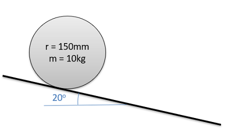
A cylinder with a radius of .15 m and a mass of 10 kg is placed on a ramp at a 20 degree angle. If the cylinder is released from rest and rolls without slipping, what is the initial angular acceleration of the cylinder? What is the time required for the cylinder to roll 5 meters?

Problem 1 Diagram

Solution:


Question 2:

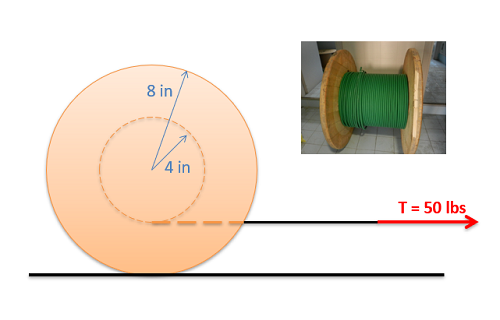
The cable spool shown below has a weight of 50 lbs and has a moment of inertia of .28 slug ft2. Assume the spool rolls without slipping when we apply a 50 lb tension in the cable.

  • What is the friction force between the spool and the ground?
  • What is the acceleration of the mass center of the spool?

Problem 2 Diagram

Spool image by Seeweb CC-BY-SA 2.0

Solution:


Question 3:

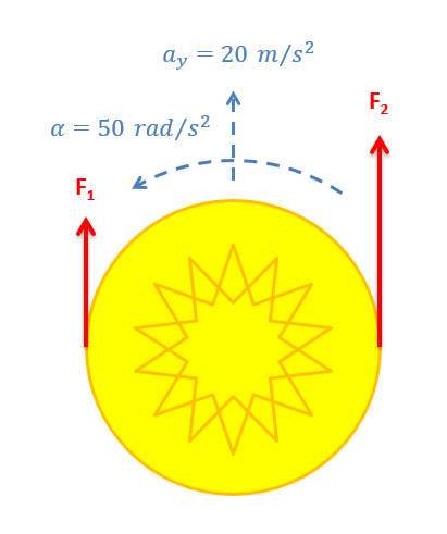
You are designing a Frisbee launcher to launch a 40 cm diameter, .6 kg Frisbee that can be modeled as flat circular disc If you want the Frisbee to have a linear acceleration of 20 m/s2 and an angular acceleration of 50 rad/s2 as shown to the right, what should F1 and F2 be?

Problem 3 Diagram

Solution:


Question 4:

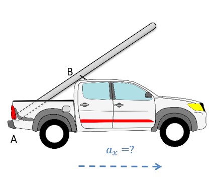
A pickup truck is carrying a 30 kg, 6 meter long ladder at a 35 degree angle as shown to the right. The ladder is wedged against the tailgate at A and makes contact with the roof of the truck at B. The distance from A to B is 2 meters. At what rate of acceleration would we expect the ladder to start to rotate upwards?

Problem 4 Diagram

Solution:


Question 5:

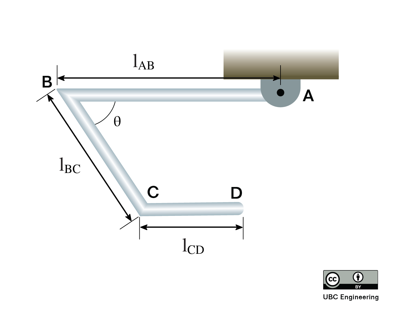
Three slender rods with equal mass are welded together. If the assembly is released from rest, what is the angular acceleration of the rods? The rods have a mass of m=2kg each. Rod AB has a length lAB=1.5m, rod BC has length lBC=1m, and rod CD has length lCD=0.5m. Initially, rod AD and rod CD are perfectly horizontal. Rod BC forms an angle of θ=45deg with rod AB.

Problem 3 Diagram

Question 6:

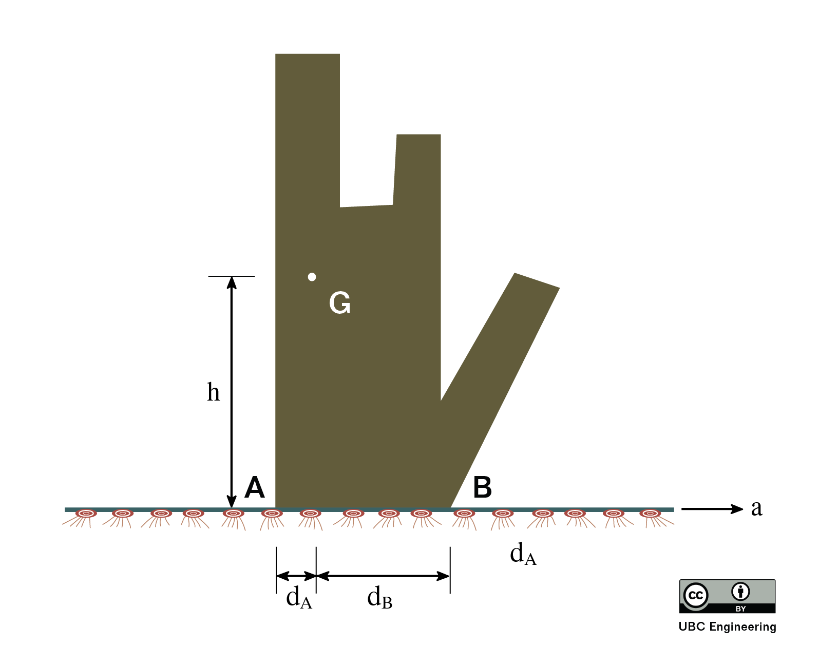
Your friend is once again trying to move their mom’s modern art sculpture by dragging a rug underneath it. Will the statue tip or slip first? Determine the magnitude of the acceleration needed for both tipping and slipping. The statue has a mass of m=80kg and has a radius of gyration kG=0.8m. The coefficient of static and kinetic friction are determined to be μs=0.25 and μK=0.2 respectively. Assume there is no friction between the rug and the ground. The center of gravity G is found a height h=1.5m and is a horizontal distance dA=0.1m from point A. Point B is a horizontal distance dB=0.35m away from the center of gravity.

Problem 3 Diagram

Question 7:

Problem 3 Diagram

Question 8:

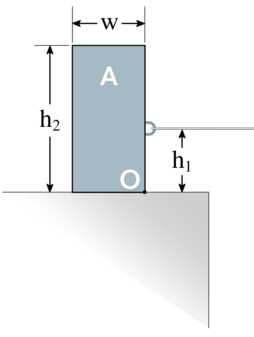
You have set up the following block such that A is connected to a rope with tension T. Block A has a mass of 12kg and height h2 = 0.8m, width w = 0.4m. The rope connects at a height h1=0.4 m and the coefficients of static and kinetic friction are given as μs=0.35 and μk=0.3. Determine if Block A tips or slips first and the force T required for this to occur.

Problem 3 Diagram