Power Screws
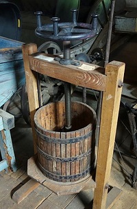
A power screw (also sometimes called a lead screw) is another simple machine that can be used to create very large forces. The screw can be thought of as a wedge or a ramp that has been wound around a shaft. By holding a nut stationary and rotating the shaft, we can have the nut sliding either up or down the wedge in the shaft. In this way a relatively small moment on the shaft can cause very large forces on the nut.
|
|
Static Analysis of Power Screws:
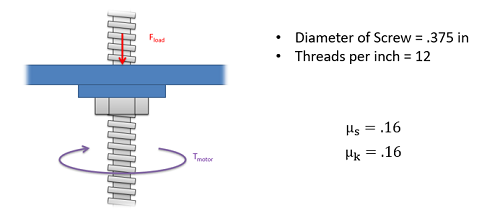
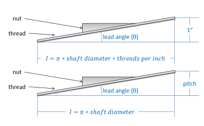
The easiest way to analyze a power screw system is to turn the problem into a 2D problem by "unwrapping" the ramp from around the shaft. To do this we will need two numbers. First we will need the diameter of the shaft, and second we will need either the threads-per-inch/centimeter or the pitch of the screw. The threads-per-inch tells you how many threads you have per inch/centimeter of screw. With a single thread design (most screws) this will also be the number of times the thread wraps around the screw in one inch/centimeter. The pitch on the other hand gives you the distance between two adjacent threads. Either of these numbers can be used to find the other.
Once we have these numbers, we can imagine unwrapping the ramp from around the screw and ending up with a ramp in one of the two situations below. In either case, we can use the inverse tangent function to find the lead angle, which can be thought of as the angle of the thread that the nut is climbing up. Finding the lead angle is the first step in analyzing a power screw system.
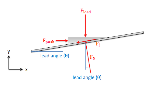
Once we find the lead angle, we can draw a free body diagram of the "nut" in our unwrapped system. Here we include the pushing force which is pushing our nut up the incline, the load force which is the force the nut exerts on some external body, the normal force between the nut and screw, and the friction force between the nut and the screw.
If our screw is pushing a load at some constant rate, then we can assume two things: First the nut is in equilibrium, so we can write out the equilibrium equations for the nut. Second the nut is sliding, indicating that the friction force will be equal to the normal force times the kinetic coefficient of friction.
| \[F_f= \mu_k*F_N\] |
| \[\sum F_x=F_{push}-F_N*sin\left ( \theta \right )-\mu _k*F_N*cos\left ( \theta \right )=0\] |
| \[\sum F_y=-F_{load}+F_N*cos\left ( \theta \right )-\mu _k*F_N*sin\left ( \theta \right )=0\] |
We can then simplify the equations above into a single equation relating the load force and the pushing force.
| \[F_{push}=\frac{sin\left ( \theta \right )+\mu_k*cos\left ( \theta \right )}{cos\left ( \theta \right )-\mu_k*sin\left ( \theta \right )}*F_{load}\] |
In reality the pushing force is not a single force at all. It is the forces preventing the nut from rotating with the screw. The cumulative pushing force will really cause an equal and opposite moment to the input moment that is spinning the shaft.
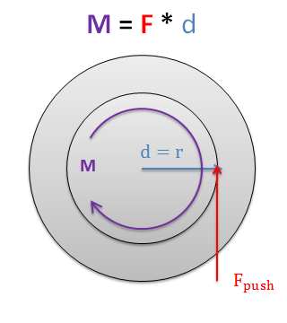
Finally, if we replace the pushing force with the moment that is driving the screw in our system (in this case torque T), we can relate the input torque that is driving our screw, to the force that the nut on the screw is pressing forward with. Screw systems are usually designed to allow fairly small input moments to push very large load forces.
| \[T=\frac{sin\left ( \theta \right )+\mu_k*cos\left ( \theta \right )}{cos\left ( \theta \right )-\mu_k*sin\left ( \theta \right )}*F_{load}*r_{shaft}\] |
Self Locking Screws
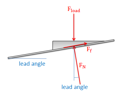
Imagine we apply a torque to a power screw to lift a body, then when we get the load to the desired height we stop applying that torque to let the body sit where it is. If we were to redraw our free body diagram from earlier for the new situation, we would find two things.
- The pushing force is missing (since a torque is no longer applied to the shaft).
- The friction is now fighting against the nut sliding back down the ramp.
With this new free body diagram, there are two possible scenarios that could occur:
- The friction force is large enough to keep the nut from sliding down the ramp, meaning everything will remain in static equilibrium if released.
- The friction force will not be sufficient to keep the nut from sliding down the ramp, meaning that the load would begin to fall as soon as the torque is removed from the shaft.
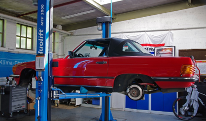
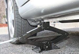
With power screw applications such as a car jack, the second option could be very dangerous. It is therefore important to know if a power screw system is self locking (option 1 from above) or not self locking (option 2 from above).
To define the boundary between self locking systems and non-self locking systems, we use something called the self locking angle. As intuition would tell us, slipping does not occur on very gentle slopes (small lead angles) while it does occur on very steep slopes (large lead angles). The angle at which the nut would begin to slip is known as the self locking angle.
To find the self locking angle, we will assume impending motion (relating the friction force to the normal force) and leave the lead angle as an unknown. This lets us create the free body diagram as shown below and gives us the equilibrium equations below.
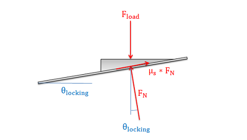
| \[\sum F_x=-F_N*sin\left ( \theta \right )+\mu_s*F_N*cos\left ( \theta \right )=0\] |
| \[\sum F_y=-F_{load}+F_N*cos\left ( \theta \right )+\mu_s*F_N*sin\left ( \theta \right )=0\] |
Using the x equilibrium equation as a starting point, we can solve for theta (eliminating the normal force all together in the process). This new equation shown below gives us the self locking angle.
| \[\theta_{locking}=tan^{-1}\left ( \mu_s \right )\] |
Systems with lead angles smaller than this will be self locking, while systems with lead angles larger than this will not be self locking.