Free Body Diagrams
A free body diagram is a tool used to solve engineering mechanics problems. As the name suggests, the purpose of the diagram is to "free" the body from all other objects and surfaces around it so that it can be studied in isolation. We will also draw in any forces or moments acting on the body, including those forces and moments exerted by the surrounding bodies and surfaces that we removed.
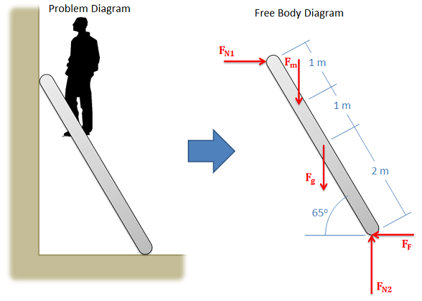
The diagram below shows a ladder supporting a person and the free body diagram of that ladder. As you can see, the ladder is separated from all other objects and all forces acting on the ladder are drawn in with key dimensions and angles shown.
Constructing the Free Body Diagram
The first step in solving most mechanics problems will be to construct a free body diagram. This simplified diagram will allow us to more easily write out the equilibrium equations for statics or strengths of materials problems, or the equations of motion for dynamics problems.
To construct the diagram we will use the following process.
- First draw the body being analyzed, separated from all other surrounding bodies and surfaces. Pay close attention to the boundary, identifying what is part of the body, and what is part of the surroundings.
- Second, draw in all external forces and moments acting directly on the body. Do not include any forces or moments that do not directly act on the body being analyzed. Do not include any forces that are internal to the body being analyzed. Some common types of forces seen in mechanics problems are:
- Gravitational Forces: Unless otherwise noted, the mass of an object will result in a gravitational weight force applied to that body. This weight is usually given in pounds in the English system, and is modeled as 9.81 (g) times the mass of the body in kilograms for the metric system (resulting in a weight in Newtons). This force will always point down towards the center of the earth and act on the center of mass of the body.
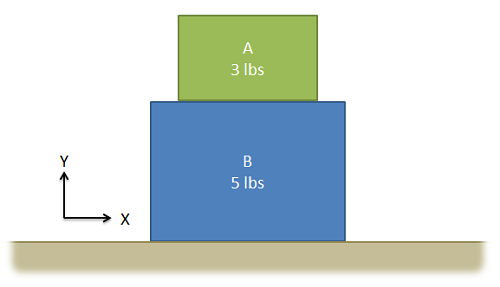
- Normal Forces (or Reaction Forces): Every object in direct contact with the body will exert a normal force on that body which prevents the two objects from occupying the same space at the same time. Note that only objects in direct contact can exert normal forces on the body.
- An object in contact with another object or surface will experience a normal force that is perpendicular (hence normal) to the surfaces in contact.
- Joints or connections between bodies can also cause reaction forces or moments, and we will have one force or moment for each type of motion or rotation the connection prevents.
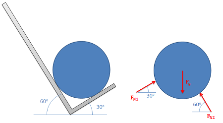
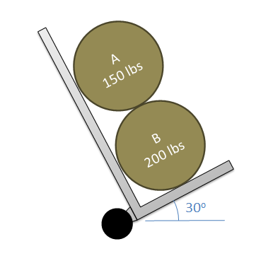
Normal forces always act perpendicular to the surfaces in contact. The barrel in the hand truck shown on the left has a normal force at each contact point. 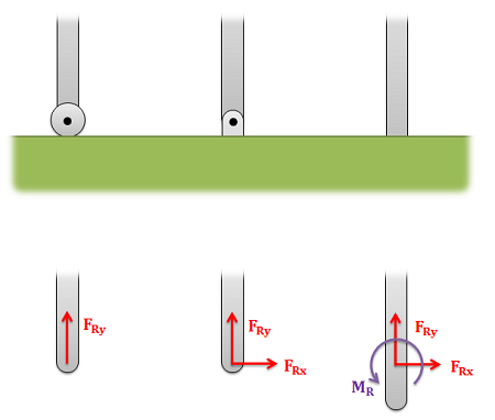
The roller on the left allows for rotation and movement along the surface, but a normal force in the y direction prevents motion vertically. The pin joint in the center allows for rotation, but normal forces in the x and y directions prevent motion in all directions. The fixed connection on the right has normal forces preventing motion in all directions and a reaction moment preventing rotation. - Friction Forces: Objects in direct contact with the body can also exert friction forces on the body, which will always resist the two bodies sliding against one another. These forces will always be parallel to the surfaces in contact. Friction is the subject of an entire chapter in this book, but for simple scenarios we usually assume rough or smooth surfaces.
- For smooth surfaces we assume that there is no friction force.
- For rough surfaces we assume that the bodies will not slide relative to one another no matter what. In this case the friction force is always just large enough to prevent this sliding.
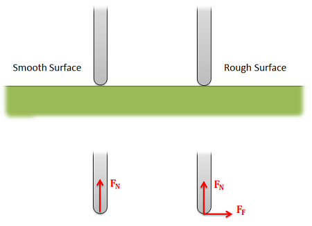
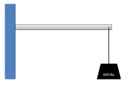
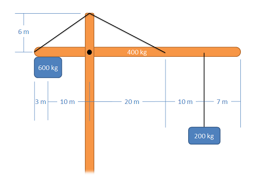
For a smooth surface we assume only a normal force perpendicular to the surface. For a rough surface we assume normal and friction forces are present. - Tension in Cables: Cables, wires or ropes attached to the body will exert a tension force on the body in the direction of the cable. These forces will always pull on the body, as ropes, cables and other flexible tethers cannot be used for pushing.
- The above forces are the most common, but other forces such as pressure from fluids, spring forces and magnetic forces may exist and may act on the body.
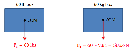
Gravitational forces always act downward on the center of mass. 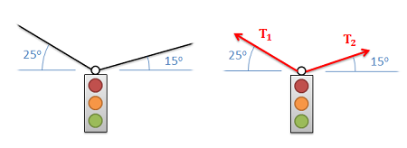
The tension force in cables always acts along the direction of the cable and will always be a pulling force. - Once the forces are identified and added to the free body diagram, the last step is to label any key dimensions and angles on the diagram.