Rigid Body Translation

With rigid bodies, we have to examine moments and at least the possibility of rotation along with the forces and accelerations we examined with particles. Some rigid bodies will translate but not rotate (translational systems), some will rotate but not translate (fixed axis rotation) and some will rotate and translate (general planar motion). Overall we will start with an examination of translational systems, then examine fixed axis rotation, then pull everything together for general planar motion.

A car braking.
The braking car in this picture is an example of a translational system. Though the car experiences a significant deceleration, it does not experience any significant rotation while it slows down. Public domain image by Sgt. Amber Blanchard.

As the start of our analysis, we will go back to Newton's Second Law. Since this is a rigid body system, we include both the translational and rotational versions. Note that now we have bodies with extent, the location of the acceleration and the axis about which we take moments or calculate mass moment of inertia are important. Linear accelerations are always measured at the center of mass. We will develop several moment equations, depending on the point about which moments are taken.

\[\sum \vec{F}=m*\vec{a_G}\]
\[\sum \vec{M_G}=I_G*\vec{\alpha}\]

As we did with particles, we can break the vector force equation into components, turning the one vector equation into two scalar equations (in the x and y directions respectively). As for the moment equation, a translational system by definition will have zero angular acceleration. With the angular acceleration being zero, the sum of the moments must all be equal to zero. This is similar to statics problems, however there is one big difference we must take into account. The moments must be taken about the center of mass of the body. Setting the moments to zero about other points will lead to invalid solutions for any body experiencing an acceleration. Putting these specifics into action, we wind up with the three base equations of motion below. To solve for unknown forces or accelerations, we simply draw a free body diagram, put the knowns and unknowns into these equations, and solve for the unknowns.

\[\sum F_{x}=m*a_{Gx}\]
\[\sum F_{y}=m*a_{Gy}\]
\[\sum M_{G}=0\]

Worked Problems:

Question 1:

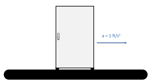
A refrigerator is 2.5 feet wide, 6 feet tall and weighs 80 lbs. The center of mass is 1.25 feet from either side and 2 feet up from the base. If the refrigerator is on a conveyor belt that is accelerating the fridge at a rate of 1 ft/s2, what are the normal forces at each of the feet?

Problem 1 Diagram

Solution:


Question 2:

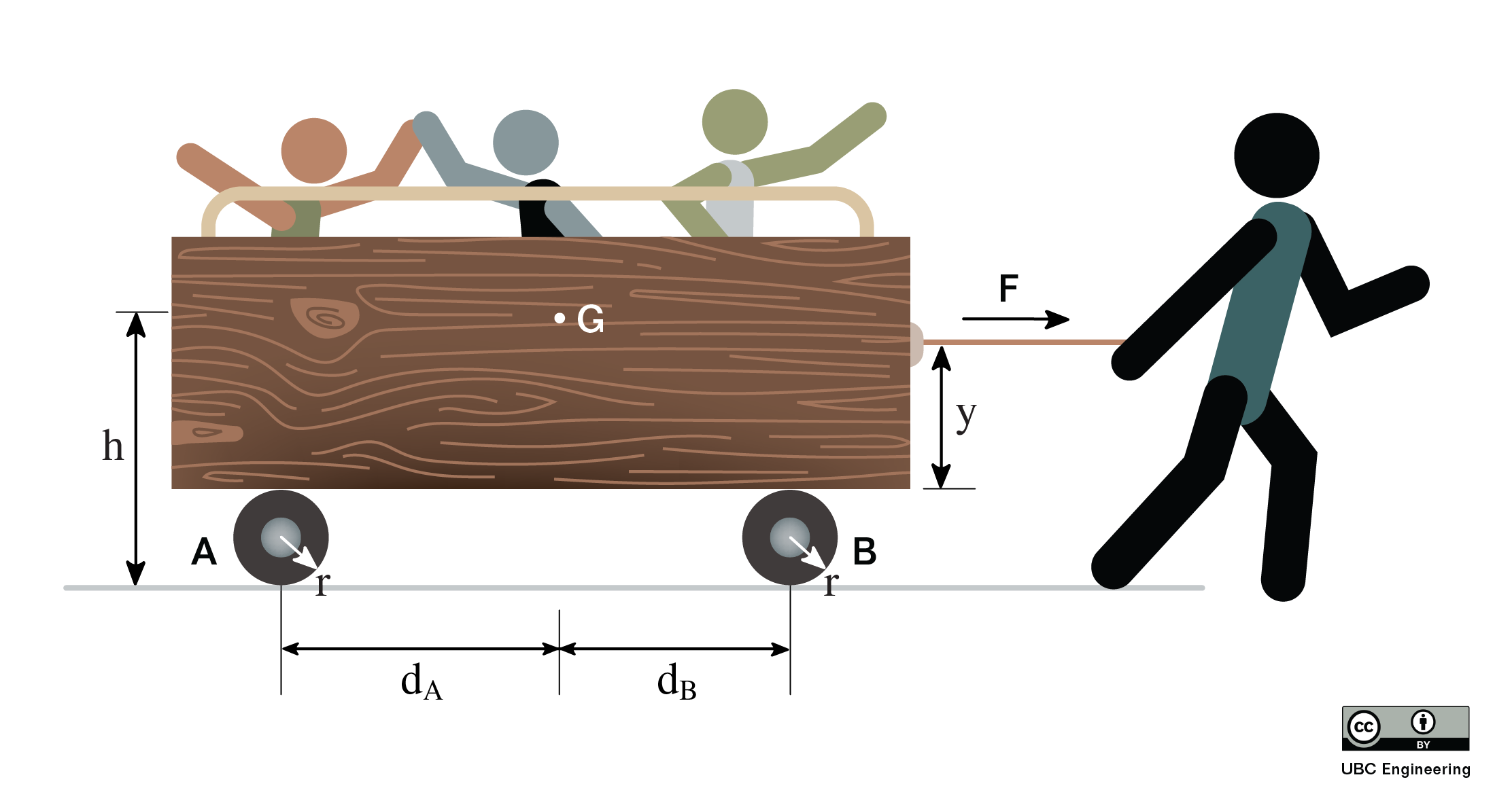
You are forced to pull a group of kindergarteners in a cart. If you apply a horizontal force of F=600 N, determine the normal force on its wheels. The cart has a total mass of m=160 kg and has a center of mass at G. Assume the wheels have negligible mass. Wheel A has a radius of 0.2 m and is a horizontal of dA=0.89 m from G. Wheel B has a radius of 0.2 m and is a horizontal distance of dB=0.39 m. You apply the horizontal force at a height y=0.5 m from the bottom of the cart. The center of gravity of G is located at a height h=1.1 m from the ground.

Problem 2 Diagram

Question 3:

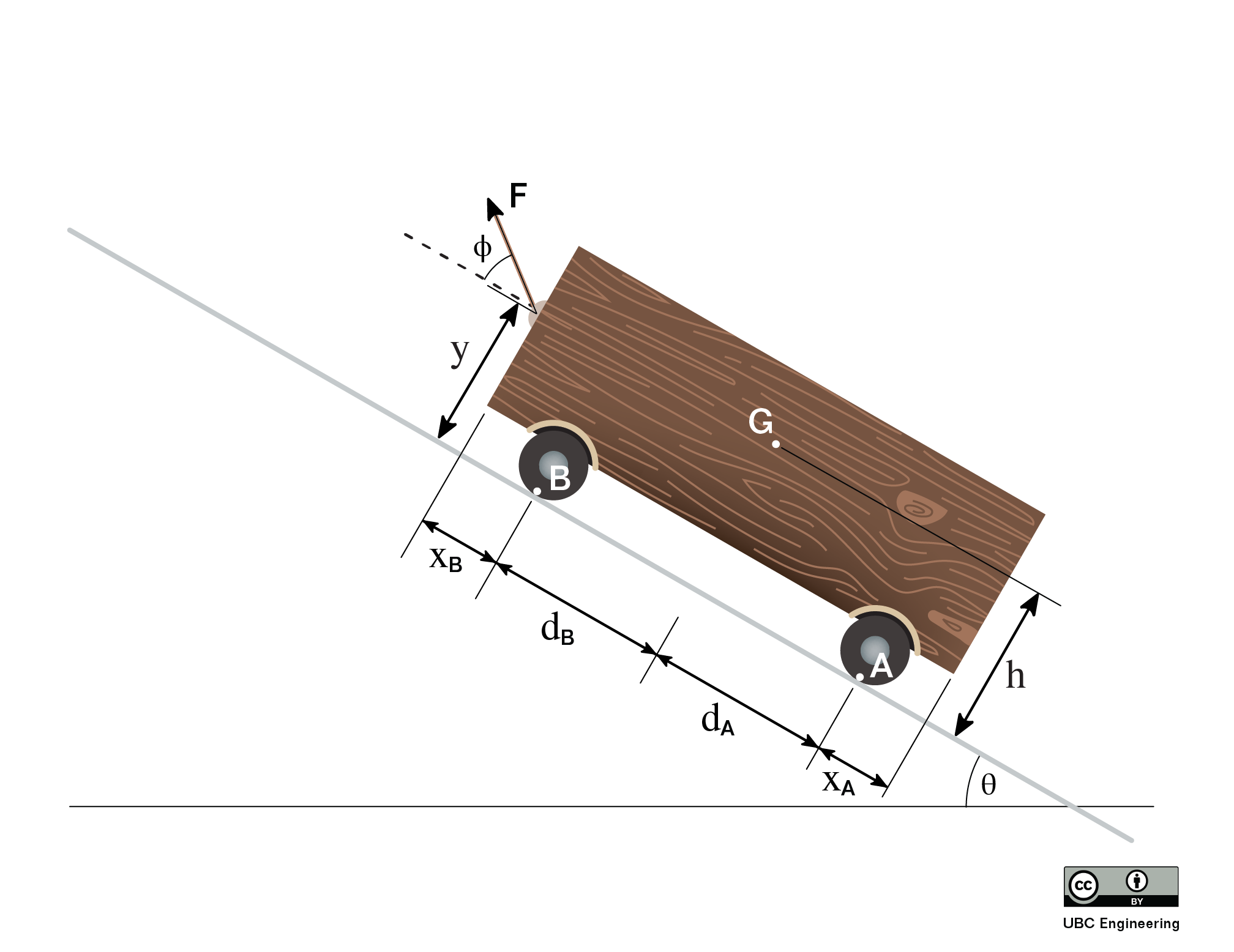
You are hauling a heavy cart up a θ=30 deg incline. Luckily, you have been working out so you can apply a force of F=500 N to the cart. If you apply this force at an angle ϕ=42 deg and the cart has a mass of m=30 kg, what is the acceleration of the cart and the normal force on each of the cart’s wheels? The cart has a center of gravity G. The force is applied at a height y=0.4 m from the ground and G is located at a height h=0.5 m. Wheel A is located xA=0.1 m from one side of the cart while wheel B is located xB=0.05 m from the other end. Wheel A is a distance dB=0.3 m from G while wheel B is a distance dB=0.25 m.

Problem 3 Diagram

Question 4:

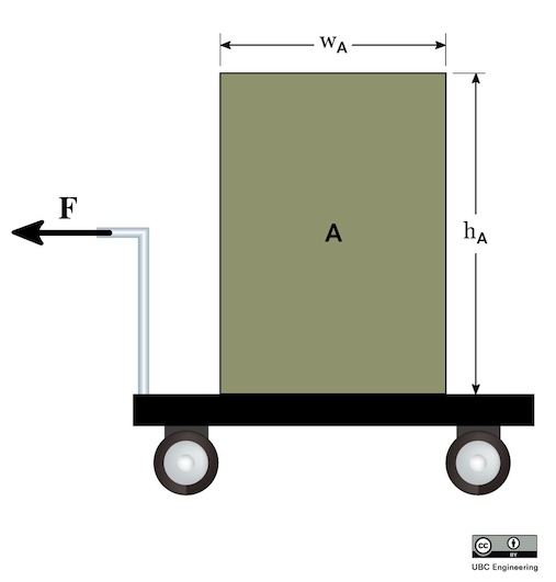
Your very wonderful parents have returned from their vacation from Hawaii while you were studying for midterms. At the airport, you stack their luggage, which can be modeled as box A. Box A has a width wA=0.5m and height hA=0.8m. If box A has a mass mA=50kg, determine the maximum force F you can apply on the 12kg car before tipping their luggage over. Assume slipping does not occur and that box A has uniform density even though clothing is probably stuffed in all sorts of places to save space for souvenirs.

Problem 3 Diagram